Thermoelectric generators (TEGs) incorporated into vehicle exhaust systems can harness waste heat from exhaust gas by converting heat energy into electrical energy via the Seebeck effect. TEGs operate efficiently over a relatively narrow temperature range – at high temperatures, thermoelectric materials can be damaged from overheating. The leading edges of a TEG may overheat before it reaches a suitably high temperature for efficient operation. Hot exhaust air must be diverted away from the thermoelectric materials to prevent such damage, at the cost of reducing system performance.
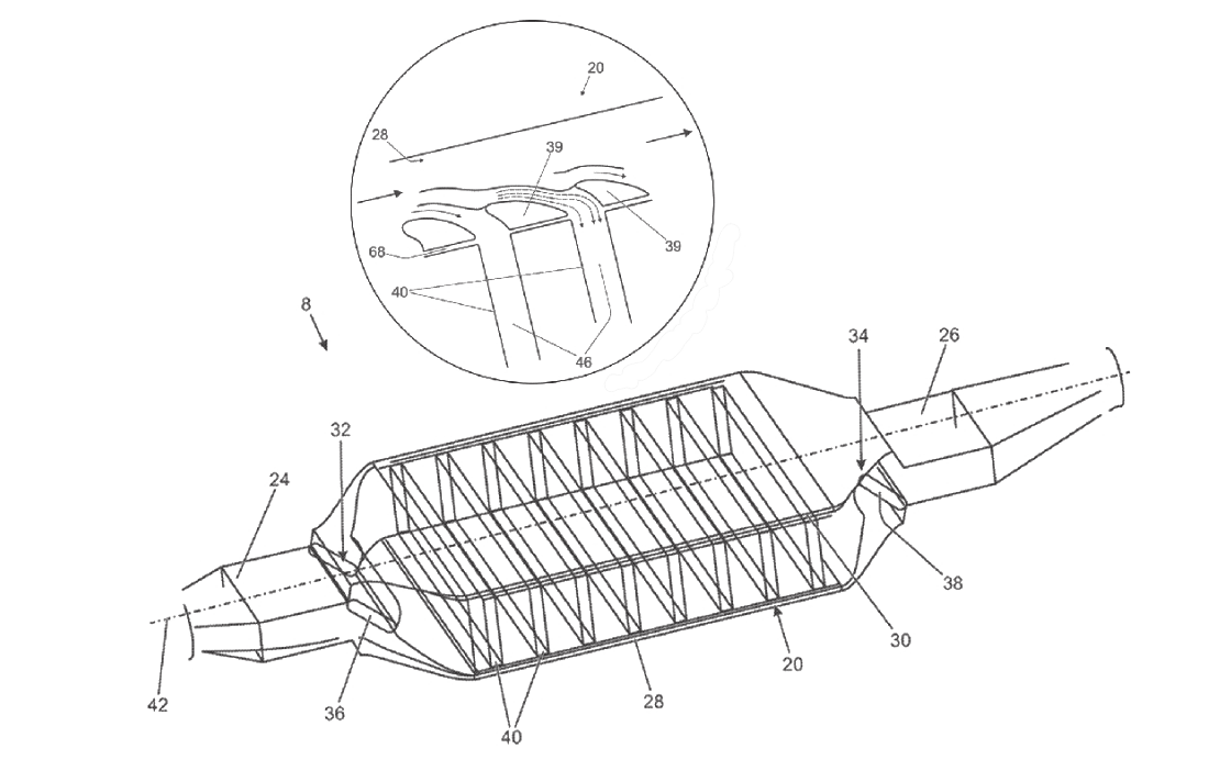
In October 2019, Jaguar Land Rover Ltd was granted UK patent GB2549123B, titled Energy recovery unit for vehicle use, which disclosed an energy recovery unit (8) for use in a vehicle exhaust system. The unit comprised an inlet (24) for receiving gas from the exhaust system and an outlet (26) for returning the gas back to it. A plurality of TEGs (40) are disposed in parallel to each other between the inlet and the outlet, at regular intervals along a main axis (42), and spaced apart to form exhaust gas passages (46) in a TEG module (20). A plurality of flow directing members (39) are positioned adjacent to the leading edges of the TEGs (40) to direct exhaust gas flow across each TEG. The flow directing members (39) promote a balanced exhaust gas flow distribution through the energy recovery unit such that each TEG receives a similar flow rate of exhaust gas.
In use, hot exhaust gas is directed through the gas passages, increasing the temperature of the hot side of heat exchanger surfaces. Meanwhile, cooling fluid is passed through a cooling pipe array in the TEG module to maintain the temperature of the cold side of heat exchanger surfaces, which produces a temperature gradient across each TEG to produce energy. The use of cooling fluid maximises this gradient and thereby the electrical output of each TEG.
The energy recovery unit may include two separate bypass ducts (28,30) positioned above and below the TEG module, connecting the inlet and the outlet. The inlet and outlet valves (32,34) with valve flaps (36,38) may control the direction of exhaust gas flow through the energy recovery unit, guiding exhaust gas flow into and out of the bypass ducts. The degree and direction of deflection of each valve flap may be controlled via actuators.
In bypass mode, the exhaust gas passes from the inlet to the outlet exclusively through one or both bypass ducts. The gas bypasses the TEG module when it is in danger of overheating, for example, due to high gas temperatures and/or prolonged gas flow. The flow directing members provide thermal barriers to separate the hot exhaust flow from the leading edges of each TEG.
In other modes of operation, some or all of the exhaust gas flows through the TEG module in a cross-flow direction, which is substantially orthogonal to the main flow direction. The flow directing members enable faster cooling of the leading edges of each TEG, increasing the amount of energy available for the TEG module in generating electricity.
In full flow mode, the valve flaps are maximally deflected in opposite directions forcing the exhaust gas through the TEG module. The direction of cross-flow through the passages may be reversed by reversing the respective deflections of the valve flaps.
In feathering mode, the valve flaps are deflected to different degrees without fully closing the bypass ducts. This allows some gas flow through the bypass ducts while forcing some of the gas into the TEG module. The feathering mode acts a combination of the bypass and full flow modes.
Read the full patent here.
This article first appeared in the January 2020 issue of Materials World, the member magazine of the Institute of Materials, Minerals and Mining.
The Patent Eye blog offers a glimpse into the future by showcasing newly granted patents. Join us as we explore the latest innovations shaping our world.
The Patent Eye blog is made available by Alphabet Intellectual Property for informational purposes, in particular, sharing of newly patented technology from granted and published patents available in the public domain. It is not meant to convey legal position on behalf of any client, nor is it intended to convey specific legal advice.
Craving intellectual stimulus? Peer into the insights brought to you by The Patent Eye and explore our latest articles.


