Ice formation on an aircraft structure may increase its weight or alter its aerodynamic properties. Any ice breaking off may damage the structure or its surroundings. Coatings developed to be ice-phobic are often applied to the leading-edge of an aircraft wing or to the rotor blades of a helicopter. The strength of ice adhesion is tested by measuring the force required to separate it from the coating. Existing test methods fail to accurately simulate ice forming conditions, including atmospheric icing whereby accreted ice is formed by supercooled water droplets freezing on contract with a structure.
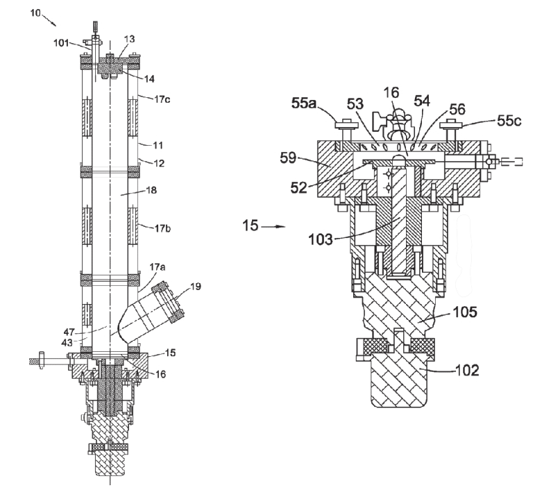
In October 2019, GKN Aerospace Services Ltd was granted UK patent GB2550427B, titled Ice test devices which disclosed an ice adhesion test device (15) comprising a test target in the form of a well (16) in which, when in use, builds up a layer of accreted ice. The target comprises a sample plate (52) at the bottom of the well and an ice-engagement element positioned circumferentially around it, providing a side wall (53) of the well. The sample plate is rotatable relative to the iceengagement element and a torque means for applying rotational torque between the sample plate and the ice-engagement element is provided. Optionally, a motor (102) connected to the sample plate via a gearing (105) within the body (59) is arranged to rotate the plate relative to the side wall. A transducer means is provided for, at least at a point at which the layer of accreted ice separates from the sample plate, measuring the rotational torque and/or the stress on the ice. Optionally, a torque ring is used to measure torque and stresses on the shaft (103).
The ice adhesion test device may form the bottom unit of a benchtop unit (10) comprising a column (1 1) defined by a side wall (12) formed of three tubular segments of wall sections (17a-c).
The side wall defines a chamber (18) which may be purged of moisture using dry nitrogen or its pressure reduced using a vacuum pump. At the top end of the chamber, a water droplet generation system comprises a nozzle device (14) with one or more nozzles in a droplet discharge device holder (13). A water temperature and pressure controller may be used to control the speed or size of the droplets, or prevent water freezing on contact with the nozzles. A viewing port (19) is provided to observe the sample, for example, a coated aluminium NS4 disc secured to the sample plate.
The temperature of each chamber portion defined by the wall sections may be controlled independently through the flow rate of cooling fluid entering the cavity of each wall section. The first wall section chamber portion (47) may be cooled by liquid nitrogen entering the cavity (43) of the first wall section (17a), the flow rate selected to provide a temperature between -15 0 C and -40 0C producing rime ice on the sample plate. Heater jackets placed around the wall sections may be used to heat portions of the chamber.
Water droplets ejected from the nozzle device are supercooled as they travel through the chamber, freezing upon impact with the sample plate. The chamber may be cooled after the water droplets impact the plate. The spray of water droplets may be continuous or periodic, for example, in forming layers of ice. The motor applies a torque turning the shaft and the sample plate against the ice adhered to the sample. Recesses (54) in the side wall (53) of the well prevent rotation of the layer of rime ice relative to said side wall. The strength of ice adhesion to the sample plate is calculated from the torque at which the ice separates from the sample plate.
Read the full patent here.
This article first appeared in the December 2019 issue of Materials World, the member magazine of the Institute of Materials, Minerals and Mining.
The Patent Eye blog offers a glimpse into the future by showcasing newly granted patents. Join us as we explore the latest innovations shaping our world.
The Patent Eye blog is made available by Alphabet Intellectual Property for informational purposes, in particular, sharing of newly patented technology from granted and published patents available in the public domain. It is not meant to convey legal position on behalf of any client, nor is it intended to convey specific legal advice.
Craving intellectual stimulus? Peer into the insights brought to you by The Patent Eye and explore our latest articles.


